
by dogger315 on 03/20/2010
This segment will cover piston, rings and cylinder installation and power valve adjustment.
Tools required: Torque adapter, torque wrench, standard assortment of metric tools.
Most people have rebuilt the top end of their ride so a lot of this information is old news. I am presenting the techniques that have worked best for me over the years. Hopefully you will see something that might be helpful the next time you tackle this job.
First order of business is protecting the crankwell from debris. Stuff a shop cloth in and around the connecting rod.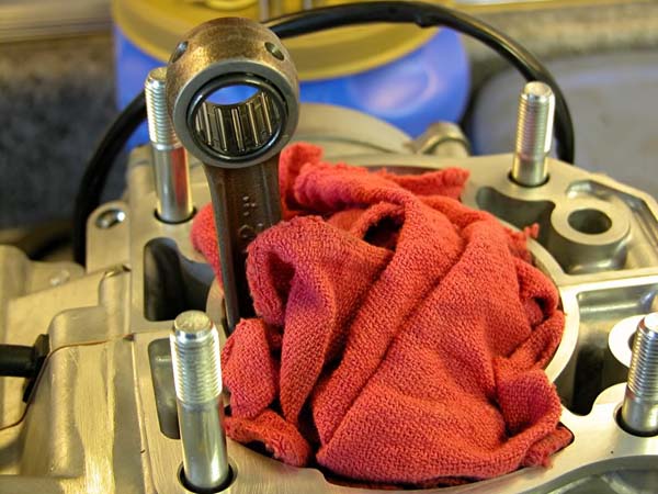
Apply oil to the cylinder studs and install with the rounded portion of the stud facing down. Use either a stud installer or a couple of nuts tightened together and torque to 9 lb.ft.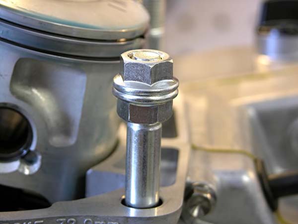
Coat the small end bearing with two stroke oil and install it into the rod.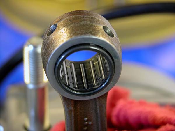
Install a circlip into position on the piston. Coat the wristpin with two stroke oil. Place the piston over the connecting rod orienting it with the skirt cutout facing aft (If you are using an OE piston, orient the piston with “IN” facing aft.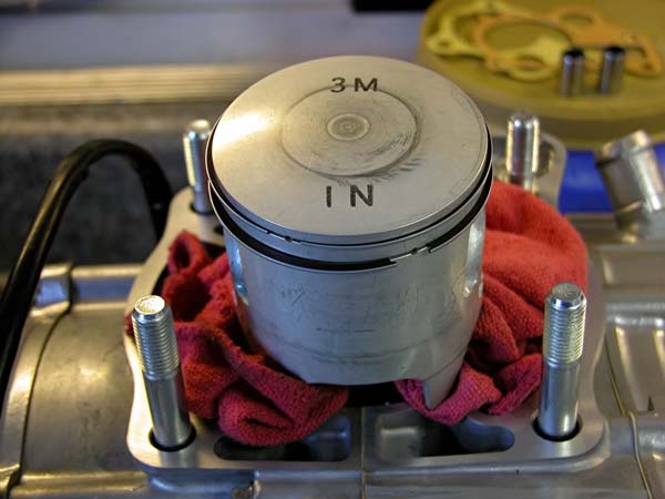
Install the other circlip insuring both are correctly seated in their grooves. Also, never re-use circlips, you’re just asking for trouble for a dollar’s worth of parts.
Apply two stroke oil to the piston rings and ring landings. Orient the rings with the mark (next to the gap) facing up and install with the ring gap straddling the pin in the ring groove.
Apply oil to the two dowel pins and install.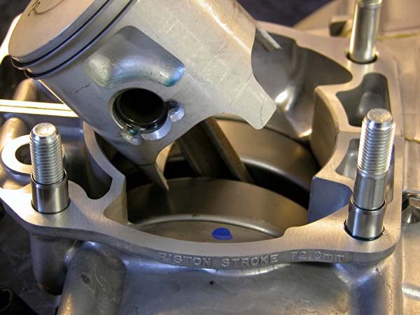
Apply grease to the pinion shaft and make sure it is oriented correctly.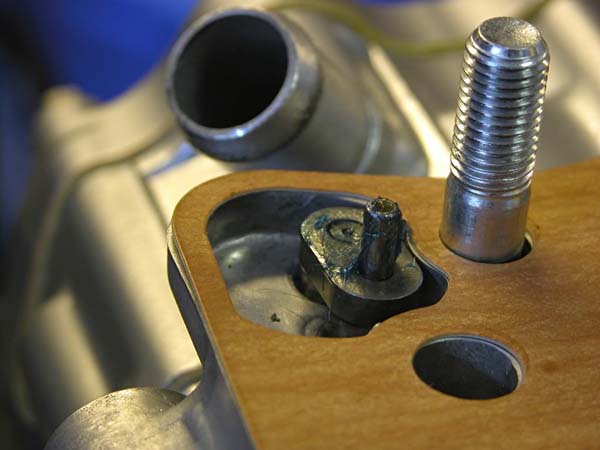
Liberally apply two stroke oil to the cylinder wall. Place the cylinder over the studs with one hand while compressing the top ring with the other. Carefully lower the cylinder over the top ring then compress the second ring and repeat. Once the cylinder is past the rings, be careful not to turn the cylinder anymore than absolutely needed to orient the cylinder over the studs – It is very easy to snag a ring on one of the ports and break it.
As you carefully lower the cylinder, take a look under the right front corner and “eyeball” the line up between the upper and lower power valve pinions, you may have to rotate the power valve clockwise slightly to get a good join up. The pin on the lower pinion goes in the gap in the upper pinion. The cylinder should seat without any gaps. If you have a gap, chances are the power valve pinions aren’t joined correctly. Simply lift the cylinder an inch or so and manipulate the power valve linkage as you lower the cylinder again.
Once the cylinder is firmly seated with no gaps, give the power valve linkage a tug to make sure it doesn’t move. Apply oil to the cylinder studs, install the four flange bolts and finger tighten. You will need the torque wrench adaptor to tighten the front two nuts. Please do not use an open end or even a box wrench and guestimate the torque. Unless you have been doing this a long time and have a calibrated hand, you are setting yourself up for a blown base gasket or possibly a warped cylinder base. Buy the adapter and do the job right.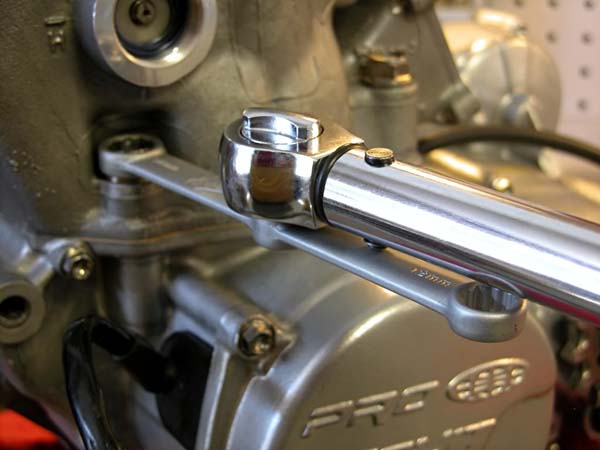
Tighten the flange bolts in a crisscross pattern in three steps.
Using the kickstarter, cycle the piston a few times. It should move freely and quietly.
Next up is the power valve adjustment. Now that the power valve is connected to the governor, the slack in the linkage can be adjusted out.
Using a 4mm hex bit on a socket wrench or a T-handle (something you can generate some torque with), loosen the socket bolt on the pinion shaft slightly. Turn the power valve fully counterclockwise and insure the flap valve is fully closed (check the reference mark on the left side inspection port points to “L”). With everything fully closed, rotate the pinion shaft slightly more to the left with the 4mm hex bit and tighten and torque to 4 lb. ft. The power valve linkage is now slightly preloaded and their should be no slack in the linkage. Honda recommends 0-0.5mm gap between the pinion spring and pinion lever for this setting. I like to set mine right at 0.5mm.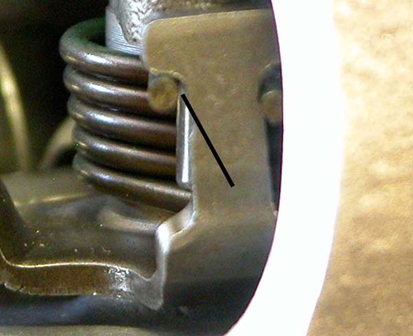
Check that the power valve position indicator is still pointing to “L”. Apply two stroke oil to a new O-ring and install the left side cover and torque to 9 lb.ft.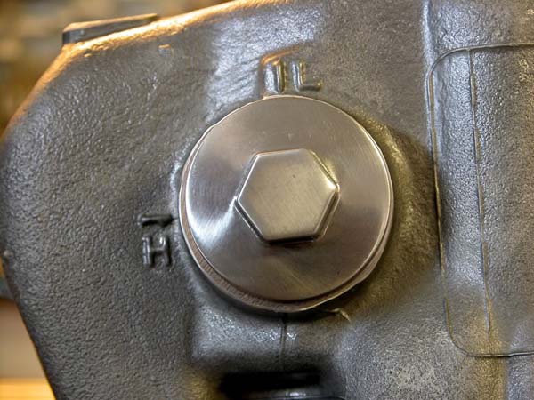
I like to spray some Permatex gasket adhesive on gaskets that don’t have alignment dowels. Just a few quick sprays of Copper spray in this case.
Let it tack up a couple of minutes and position the gasket right where you want it. This spray is available in Copper (hot areas) and silicone and is also good insurance for areas like center case gaskets.
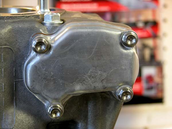
Install the right side power valve cover and torque the bolts to 9 lb.ft.