
by dogger315 on 02/11/2010
In part two of the CR250 engine build we will cover crankshaft, transmission and gear shift components.
Tools you will need: crankshaft installer/remover, engine stand, service manual, circlip pliers and a typical metric tool assortment
Tusk Crank Puller/Installer
I use a crank installing/removing tool to install the crankshaft. Probably the worst thing you can do, is pound on the crankshaft with a hammer. That will most likely knock the crank halves out of alignment and the bike will feel like a jackhammer when running (assuming it will still run).
Several tool companies sell these tools as well as some of the manufacturers. I use and recommend an inexpensive model sold by
Rocky Mountain Cycle/ATV under their Tusk brand.
The crank installer simply thread into the primary gear threads and with a nice slow controlled process, draws the crankshaft into the main bearing.
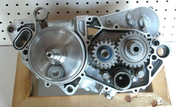
Another useful item is an engine stand. You can make this out of a length of 2X4 lumber. the stand is a rectangular box measuring 12? by 10? outside. Cut the four lengths of wood and place them on end and screw them together with wood screws. This stand will allow you to place the center case flat with the crankshaft installed.
Crankshaft installation. Place the primary gear side of the crankshaft (the short side) into the right center case main bearing and attach the crank installer from the other (clutch) side. Make sure the crank is square in the bearing and begin tightening the installer. You will know when it is seated by the sound and the increased resistance to tightening. Remove the installer and spin the cramk to make sure it spins freely and quietly.
Transmission gear cluster assembly. This looks complicated but with a Honda Service manual and close attention to detail, it is simple and straight forward. One “gotcha”; There are two 23T sprockets in the cluster. Both are the same color (black), both have the same size hole and both are interchangeable. If you manage to put the countershaft sprocket on the mainshaft or vice versa, The clusters will mesh and will spin in the cases but will bind and freeze solid when you install the left side center case. The only difference betwwen the two gears is one is slightly thinner (cross section) than the other. The thin 23T gear goes on the MAINSHAFT.
It is very important that the snap rings and washers are installed correctly. If you look closely, the snap rings and some washers have a rounded edge on one side and a straight machined edge on the other. The service manual shows these edges in silhouette to facilitate correct orientation. Disregarding this or getting it wrong will invite premature wear and failure.
Assemble each gear cluster per the manual then place them together to insure proper meshing. MAKE SURE ALL THE THRUST WASHERS AND CIRCLIPS ARE INSTALLED IN THE CORRECT LOCATION. Place a rubber band around each cluster to keep the thrust washers in place, coat them with clean transmission fluid (gearbox or 10W-40 not ATF) and mesh them together. Place the meshed clusters in the same center case you just installed the crankshaft in. Remove the rubber bands and spin the clusters. They should spin freely and quietly.
Next, install the shift drum in it’s bearing and spin it. The last items to install are the shift forks and shafts. The shift forks are marked with a “4L, 4R and 4C”. The 4L and 4R are used on the countershaft or right side cluster.
Place the shift forks onto the gear races – The 4R goes on first with the 4R stamp facing up and the pin facing toward the shift drum followed by the 4L in the same orientation. Manipulate the countershaft gear cluster up and down to allow placement of the pins in the bottom most and upper most groove in the shift drum. Once that is done, install the shift fork shaft into the case. The remaining shift fork is used on the mainshaft or left side cluster. Place the shift fork onto the single gear race with the 4C facing down. Insert the
pin into the middle and only remaining groove in the shift drum and install the shift fork shaft.
Finish up by spinning the gear clusters and turning the shift drum by hand to check for obstructions or binding.
That is the whole shabang for center case assembly.

“loaded” case and view of well used engine stand. Transmission assembly clockwise from top left: Mainshaft, countershaft, countershaft shift forks and shaft, shift drum and mainshaft shift fork and shaft
Stay tuned for Part 3…